
Hardware overview
The Caterpillar SSR is a dedicated controller for stepper-motor driven roll-off roofs. It connects over USB or WiFi and integrates with ASCOM-compatible automation software to open and close the roof automatically.
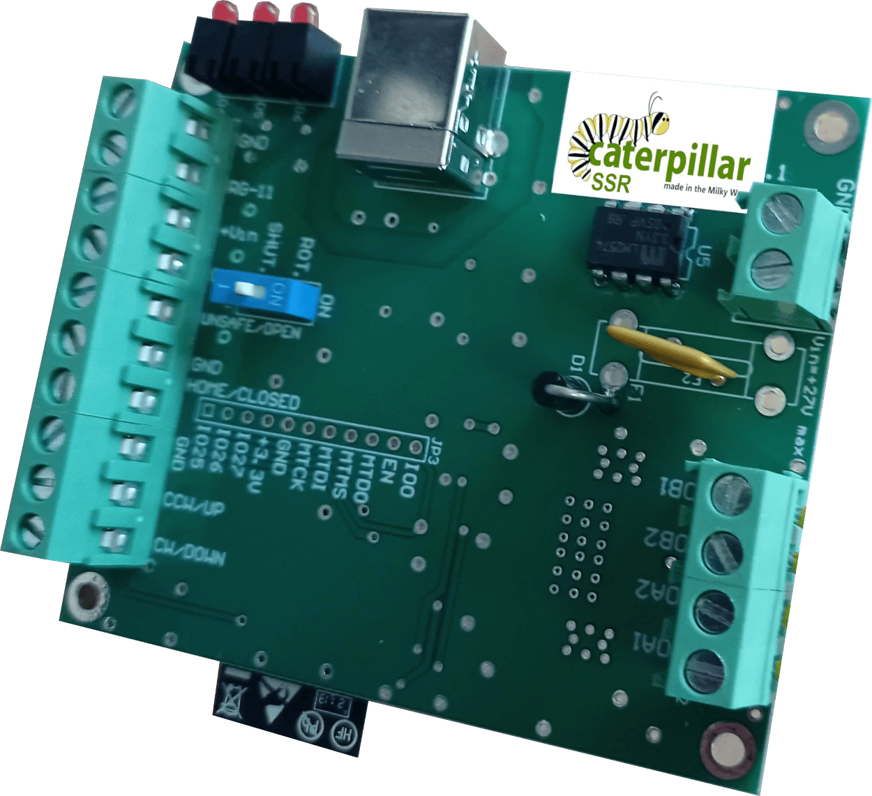
What you'll need
| Stepper motor | Bipolar stepper (see stepper wiring section for specifications) |
| Limit switches | Open and closed positions (both required) |
| Power supply | DC supply (see stepper wiring section for voltage range) |
Need: board photograph with labelled connectors, full what's-in-the-box list, and complete technical specifications.
Stepper motor wiring
The Caterpillar SSR drives a bipolar stepper motor from its onboard driver.
Need: connector type, pin assignment (A+, A−, B+, B−), how to identify motor winding pairs, current rating, supply voltage range, and microstepping configuration.
Do not connect a motor that exceeds the onboard driver's current rating. Check your motor's datasheet before connecting.
Limit switches
Two limit switches are required, one for the fully-open position and one for the fully-closed position. The controller uses these to stop the motor and confirm the roof has reached its target.
Need: connector pinout, switch type (normally-open or normally-closed), wiring diagram, and guidance on switch placement and adjustment.
ASCOM roof driver
The Caterpillar SSR uses an ASCOM dome driver configured for roll-off roof operation. It exposes the roof as a dome with a single shutter (open/close) and no rotation axis. The driver is included in the same installer as the standard Caterpillar: Caterpillar-Install.exe.
Need: confirm whether SSR uses the same driver as the dome Caterpillar (with a different profile) or a separate driver. Configuration options specific to SSR.
ASCOM Device Hub setup
ASCOM Device Hub lets multiple astronomy applications share a single dome driver connection, and handles telescope-dome slaving so the dome follows the telescope automatically.
Some programs—such as Voyager, Sequence Generator Pro, or N.I.N.A.—include their own dome to telescope slaving. It is up to you to choose the software to synchronise both elements. The ASCOM Device Hub is used here for reference.
Connecting the dome driver
- Open ASCOM Device Hub.
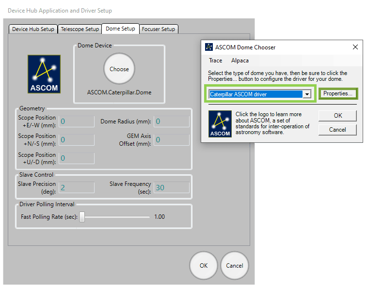
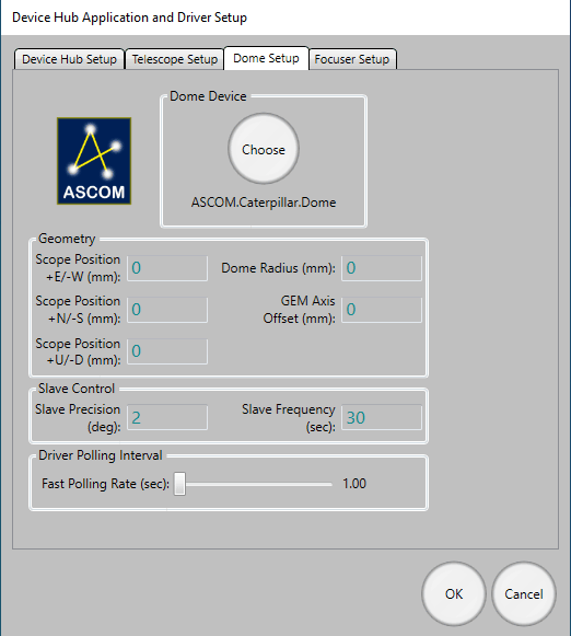
- Go to Tools → Setup → Dome Setup.
- Click Choose and select the Caterpillar ASCOM driver.
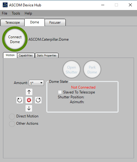
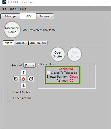
- Click Connect.
Telescope slaving
Configure the Telescope tab to connect to your mount's ASCOM driver, then enable slaving. Recommended parameters:
| Slave precision | 2° |
| Slave frequency | Every 5 seconds |
| Driver polling | Every 2 seconds |
Dome geometry
For accurate slaving, you need to tell Device Hub the physical geometry of your dome and mount. Open Dome Setup → Geometry and enter:
| Dome Radius | The inside radius of the dome |
| GEM Axis Offset | Distance from the GEM pier to the dome's geometric centre |
| E/W Offset | East–West offset of the mount's intersection point from dome centre |
| N/S Offset | North–South offset |
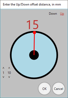
| Up/Down Offset | Vertical offset |
The N/S, E/W, and Up/Down parameters describe by how much the mount's optical axis intersection point is offset from the centre of rotation of the dome. The best way to measure these is often by taking differences—position the telescope at different azimuths, note the dome positions required, and back-calculate the offsets.
ASCOM Safety Monitor
The safety monitor driver is included in the same installer as the dome driver ( Caterpillar-Install.exe), and allows your automation software to close the observatory automatically when unsafe conditions are detected. It is fully compatible with the Lunaticoastro CloudWatcher and other monitors such as Hydreon's rain gauges.
Need: full configuration instructions for the Safety Monitor driver — how to configure the unsafe condition thresholds and which inputs are supported.
INDI driver
A dedicated INDI driver is coming soon. In the meantime, the Caterpillar is fully compatible with the Nexdome Beaver INDI driver, which is included with the default drivers, and that one can be used.
If you encounter issues with INDI support, please get in touch with us at support@lunaticoastro.com.
Connection issues
Board not appearing as a COM port
Install the CP210x driver: CP210x_Universal_Windows_Driver.zip. Try a different USB cable (some cables are charge-only and carry no data), and try a different USB port on your computer.
Connection drops unexpectedly
You should disable the power saving feature of the USB port. In Device Manager, find the CP210x device under Ports (COM & LPT), open its Properties → Power Management, and uncheck "Allow the computer to turn off this device to save power".
Cannot connect over WiFi
- Verify the IP address; check your router's DHCP table, or reconnect via USB to see the current address shown in Initial motor configuration and settings.
- Make sure the board and the PC are on the same network.
- Check that no firewall is blocking UDP port 10000.
- Confirm that Station mode is enabled and the board has successfully joined your network.
Shutter board not connecting
- The rotator↔shutter link is a private, internal Wi-Fi connection that pairs automatically—no network settings to check here. If it is not coming up, power-cycle both boards.
- Make sure both boards are powered and within range of each other.
- Initial motor configuration and settings waits up to 30 seconds for the shutter, be patient after connecting the rotator.
Unexpected stops
System stops with a warning during homing
Should the home sensor not be found after a complete revolution, the system will stop and issue a warning. Check:
- Home sensor wiring and connector.
- That the sensor is positioned to trigger as the dome passes. Test manually by activating the sensor while watching its indicator in the Sensors panel of Initial motor configuration and settings.
- For hall-effect sensors: confirm the magnet is close enough and correctly oriented.
- For mechanical sensors: check the plunger is not obstructed.
System stops with a warning during rotation
If the encoder does not detect motion when the dome is running, the system will stop. Check encoder wiring and connections, and verify the encoder is spinning when the dome moves.
Other issues
Calibration fails or aborts unexpectedly
- Check encoder wiring, a loose connection will cause no position feedback.
- Reduce the physical max speed in Initial motor configuration and settings and retry; the motor may be losing steps under load at high speed.
- Make sure the dome can complete a full unobstructed cycle during calibration.
Dome position drifts over time
- Re-run calibration, the encoder mapping may be stale after a motor or dome modification.
- Check that calibration data was saved to flash after the last successful calibration.
Dome not reaching target azimuth
- Check the logical speed range, if logical min is set too low, the derived motor speed may fall below physical min and the motor will not turn.
- If the motor runs but the dome barely moves, check the mechanical coupling.
Need: LED status indicator meanings (connected, AP mode, STA searching, etc.) and factory reset procedure.