
Hardware overview
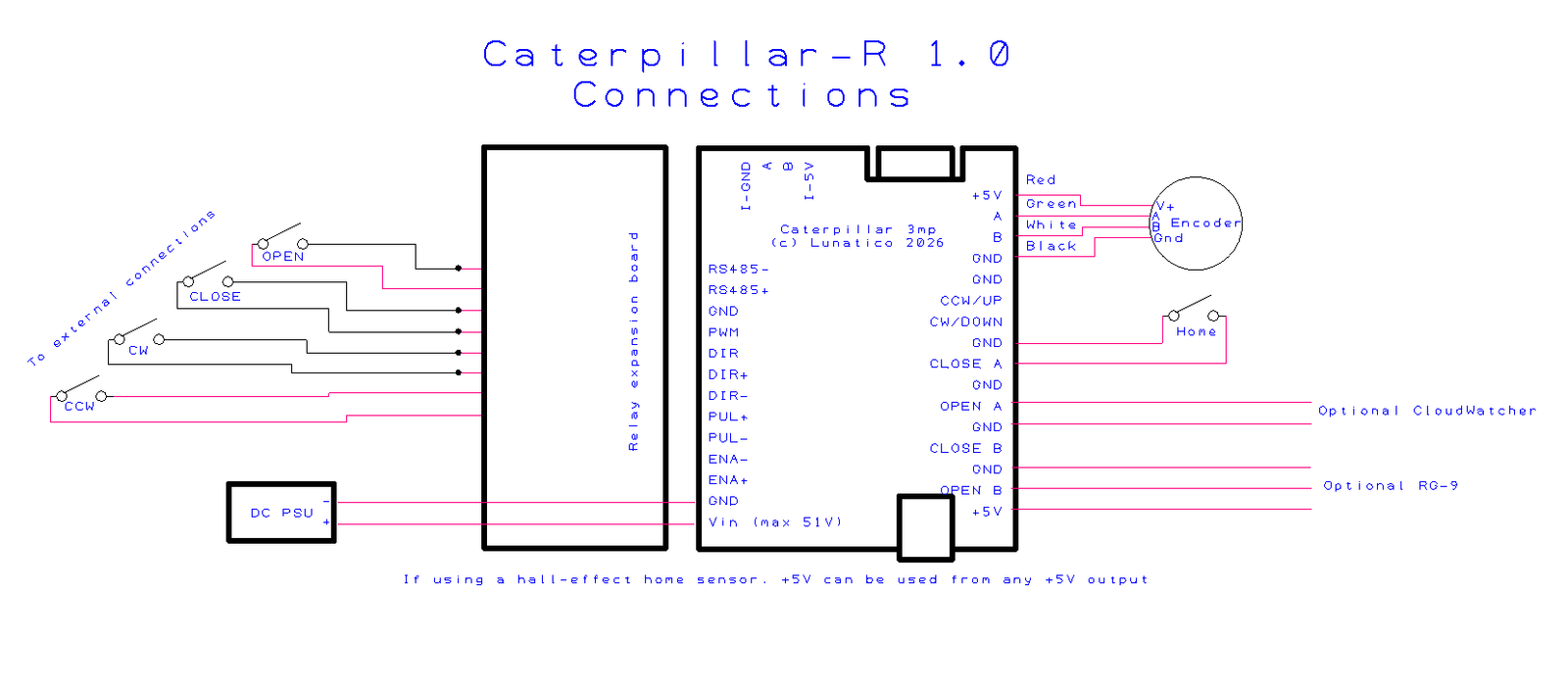
The CaterpillarR is the Caterpillar model that works with relays (hence the R). It is designed to retrofit existing observatories with manual operation. For observatory domes designed to be operated by four buttons—to open the shutter, close it, rotate clockwise, and rotate counter-clockwise—the CaterpillarR automates these functions via four relays, wired in parallel with the buttons on the control unit.
Connect your computer to the CaterpillarR with a USB cable and turn it on. Windows will detect a new device and may install the drivers automatically. You will also need to install the CP210x driver and disable the USB power saving feature (see the Connecting via USB section for details).
What you'll need
| Existing motor system | With accessible CW, CCW (and optionally Open, Close) button contacts |
| USB cable | To connect the board to the PC running your ASCOM software |
| Encoder | For precise azimuth positioning |
| Home sensor | For azimuth reference after power cycle |
Relay connections
The CaterpillarR automates dome functions via four relays, wired in parallel with the existing buttons on the control unit. Each relay output corresponds to one button:
| CW | Clockwise dome rotation |
| CCW | Counter-clockwise dome rotation |
| Open | Shutter / flap open |
| Close | Shutter / flap close |
The relay acts as a dry contact (equivalent to pressing the button), so no additional power supply is needed from the CaterpillarR side. End-of-travel detection comes from the existing motor system, just as with manual button operation.
If your dome's shutter has flaps (AKA lower shutters) as a distinct element from the main opening, see Flaps (lower shutters) for how they are handled on this model.
Identify your existing control panel's button terminals with a multimeter before connecting. Verify that the button contacts are isolated from mains voltage, the CaterpillarR relays are rated for low-voltage control signals only.
Need: connector type and pin numbering on the CaterpillarR board, relay specs (max switching voltage and current).
Flaps (lower shutters)
Some domes split the shutter into a main opening and separate flaps (AKA lower shutters), each with its own manual Open/Close buttons on the control panel. Because the CaterpillarR automates whatever buttons your existing system exposes (see Relay connections), whether flaps can be driven independently from the main opening depends on your existing button wiring, not on the CaterpillarR itself.
- If your control panel has a single pair of Open/Close buttons that move both the opening and flaps together, wiring the CaterpillarR's Open/Close relays in parallel with that pair is enough—no separate setup is needed for flaps.
- If your control panel has a distinct pair of buttons dedicated to the flaps, a second relay pair is required to automate them independently from the opening.
Need: confirm whether the standard 4-relay CaterpillarR board supports a second Open/Close relay pair for independently-controlled flaps, or whether that requires an expansion board. If supported, document the extra connector and how to enable/configure it in software.
Encoder
Rotation of the dome is measured by a rotary encoder, and the home position is confirmed by a proximity switch. The combination of these allows for very precise positioning of the dome.
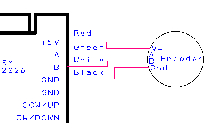
Need: compatible encoder types.
Home sensor
A home sensor provides a fixed azimuth reference that the controller can use to re-establish its position after a power cycle.
The same sensor types supported by the standard Caterpillar—mechanical push-button or hall-effect NPN—can be used here. See the Home sensor section of the standard Caterpillar documentation for sensor selection and mounting guidance.
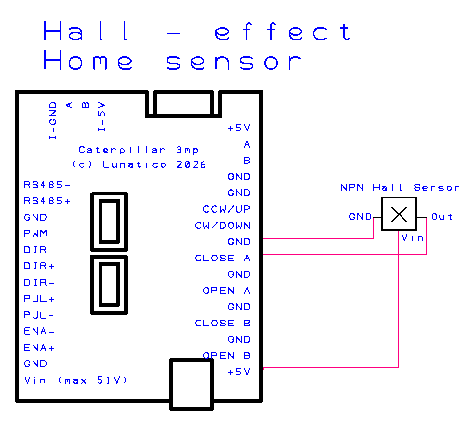
Need: wiring pinout for other home sensors connector on the CaterpillarR board. &Confirm the above text.
Voltage monitor
The voltage monitor (part of the Caterpillar board) allows the CaterpillarR to read a supply or battery voltage and report it through the ASCOM Safety Monitor interface. This can be used to trigger automatic close procedures if the supply voltage drops below a safe threshold.
Need: connector pinout, acceptable input voltage range, how to configure the threshold in software, and whether a resistor divider is needed for higher voltages. REVISAR.
ASCOM dome driver
The Caterpillar's software includes the ASCOM dome driver and is available from this link. It has two components: the dome driver and a safety monitor driver for the optional weather input (a CloudWatcher can be used for this purpose).
The ASCOM Platform must be installed before running the Caterpillar installer. The software and drivers are the same for both the Caterpillar and the CaterpillarR.
Selecting the driver
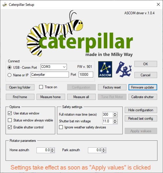
In your astronomy software's dome chooser, select Caterpillar Dome from the list. Open the driver's Setup dialog to configure the connection before connecting for the first time.
Connect
Enter the board's IP address (for WiFi) or select the COM port (for USB); the board communicates on UDP port 10000. The dialog also shows the connected board's firmware version (FW v.), and Firmware update lets you flash a new one without leaving the driver.
Open log folder and Trace on are diagnostic aids—enable tracing and reproduce an issue to be able to send the logs for support. Configuration / Hide configuration toggles the extended panel described below, and Factory reset resets the driver's own settings back to defaults.
Homing and calibration
These buttons perform the same kind of homing/calibration work as Motor and encoder calibration in Initial motor configuration and settings, but from the driver itself, without needing to reconnect with that tool:
| Find home | Drives the dome until it locates the physical home sensor. |
| Measure home | Finds the home sensor, then sweeps back and forth across it to precisely measure its trigger point from both directions. |
| Measure all | Measures the full circumference together with the home sensor; the complete calibration. |
| Tune Rot Motor | Matches the motor to the encoder, the same operation Initial motor configuration and settings performs, but for a different board revision; on the Caterpillar it is normally disabled. |
| Calibrate shutter | Measures the distance between the shutter's open and close limit switches. |
Options
| Use status window | Shows a small floating status window. |
| Status window always visible | Keeps that window on top at all times, instead of only when relevant. |
| Enable shutter control | Activates the shutter commands/buttons when a shutter board is present. |
Safety settings
| Full rotation max time (secs) | The longest a full rotation should take; if exceeded, the driver treats the dome as stuck and faults instead of spinning indefinitely. |
| Shutter bat min voltage | If the shutter's independent battery drops below this voltage, the shutter closes automatically. |
| Ignore weather safety devices | Lets the shutter open, and keeps it from auto-closing, even while the Safety Monitor reports unsafe weather. Use at your own discretion. |
This bypasses a safety feature meant to protect your equipment from weather—only enable it if you understand the risk (e.g. bench testing indoors, or taking sky flats under conditions the safety monitor would otherwise flag as unsafe).
Rotator parameters
Home azimuth is the real-world azimuth, in degrees, that corresponds to the home sensor position; Park azimuth is where the dome should move to when parking.
There is no separate "save" step—settings take effect as soon as you click Apply values. Reload last config discards any unapplied changes and reloads the last saved values instead.
Status window
Checking Use status window opens a small floating window with live status and quick manual controls—handy for keeping an eye on the dome without opening your full automation software.
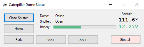
| Dome / Shutter | Connection and open/close state at a glance. |
| Battery | The shutter's independent battery voltage (see Shutter bat min voltage above). |
| Azimuth | The dome's current azimuth. |
| Close Shutter (toggles to Open Shutter) | Opens or closes the shutter. |
| Home / Park | Send the dome to its home or park position. |
<<<< / >>>> | Rotate the dome manually, one direction each. |
| Stop all | Immediately stops all motion, rotation and shutter alike. |
ASCOM Device Hub setup
ASCOM Device Hub lets multiple astronomy applications share a single dome driver connection, and handles telescope-dome slaving so the dome follows the telescope automatically.
Some programs—such as Voyager, Sequence Generator Pro, or N.I.N.A.—include their own dome to telescope slaving. It is up to you to choose the software to synchronise both elements. The ASCOM Device Hub is used here for reference.
Connecting the dome driver
- Open ASCOM Device Hub.
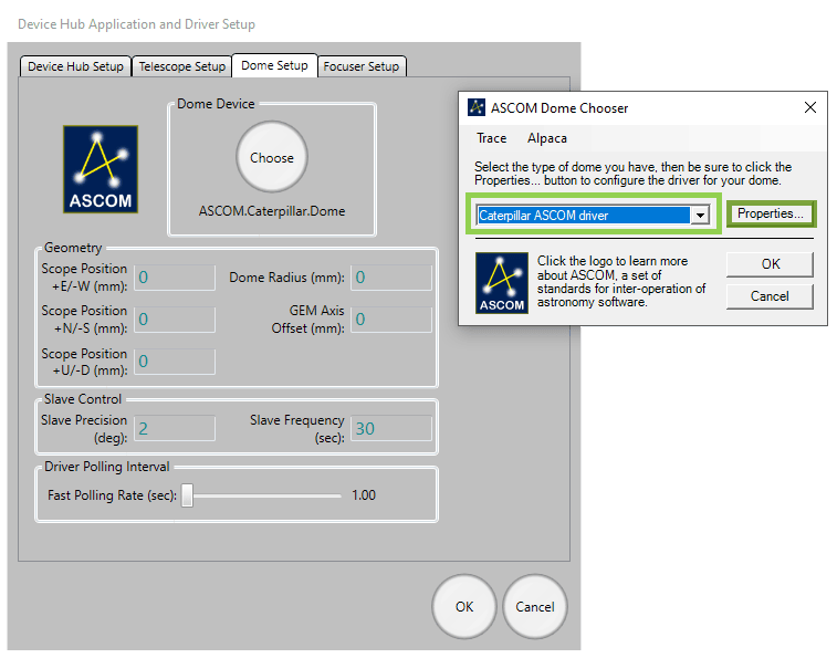
- Go to Tools → Setup → Dome Setup.
- Click Choose and select the Caterpillar ASCOM driver.
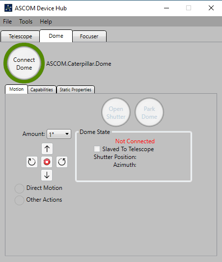
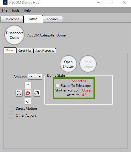
- Click Connect.
Telescope slaving
Configure the Telescope tab to connect to your mount's ASCOM driver, then enable slaving. Recommended parameters:
| Slave precision | 2° |
| Slave frequency | Every 5 seconds |
| Driver polling | Every 2 seconds |
Dome geometry
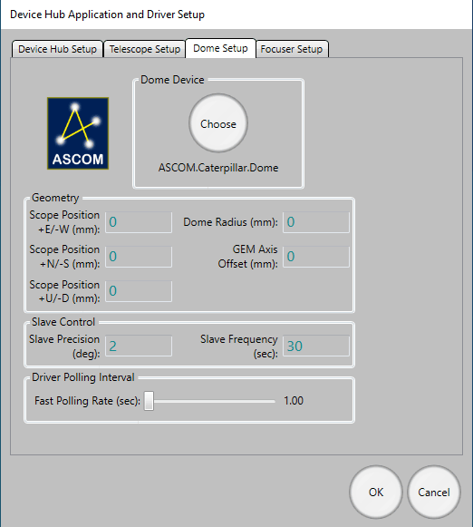
For accurate slaving, you need to tell Device Hub the physical geometry of your dome and mount. Open Dome Setup → Geometry and enter:
| Dome Radius | The inside radius of the dome |
| GEM Axis Offset | Distance from the GEM pier to the dome's geometric centre |
| E/W Offset | East–West offset of the mount's intersection point from dome centre |
| N/S Offset | North–South offset |
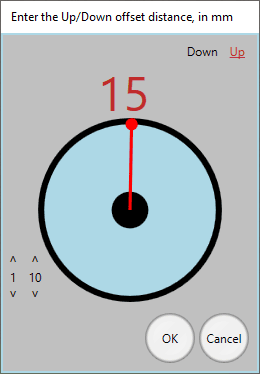
| Up/Down Offset | Vertical offset |
The N/S, E/W, and Up/Down parameters describe by how much the mount's optical axis intersection point is offset from the centre of rotation of the dome. The best way to measure these is often by taking differences—position the telescope at different azimuths, note the dome positions required, and back-calculate the offsets.
ASCOM Safety Monitor
The safety monitor driver is included in the same installer as the dome driver ( Caterpillar-Install.exe), and allows your automation software to close the observatory automatically when unsafe conditions are detected. It is fully compatible with the Lunaticoastro CloudWatcher and other monitors such as Hydreon's rain gauges.
Need: full configuration instructions for the Safety Monitor driver — how to configure the unsafe condition thresholds and which inputs are supported.
INDI driver
A dedicated INDI driver is coming soon. In the meantime, the Caterpillar is fully compatible with the Nexdome Beaver INDI driver, which is included with the default drivers, and that one can be used.
If you encounter issues with INDI support, please get in touch with us at support@lunaticoastro.com.
Connection issues
Board not appearing as a COM port
Install the CP210x driver: CP210x_Universal_Windows_Driver.zip. Try a different USB cable (some cables are charge-only and carry no data), and try a different USB port on your computer.
Connection drops unexpectedly
You should disable the power saving feature of the USB port. In Device Manager, find the CP210x device under Ports (COM & LPT), open its Properties → Power Management, and uncheck "Allow the computer to turn off this device to save power".
Cannot connect over WiFi
- Verify the IP address; check your router's DHCP table, or reconnect via USB to see the current address shown in Initial motor configuration and settings.
- Make sure the board and the PC are on the same network.
- Check that no firewall is blocking UDP port 10000.
- Confirm that Station mode is enabled and the board has successfully joined your network.
Shutter board not connecting
- The rotator↔shutter link is a private, internal Wi-Fi connection that pairs automatically—no network settings to check here. If it is not coming up, power-cycle both boards.
- Make sure both boards are powered and within range of each other.
- Initial motor configuration and settings waits up to 30 seconds for the shutter, be patient after connecting the rotator.
Unexpected stops
System stops with a warning during homing
Should the home sensor not be found after a complete revolution, the system will stop and issue a warning. Check:
- Home sensor wiring and connector.
- That the sensor is positioned to trigger as the dome passes. Test manually by activating the sensor while watching its indicator in the Sensors panel of Initial motor configuration and settings.
- For hall-effect sensors: confirm the magnet is close enough and correctly oriented.
- For mechanical sensors: check the plunger is not obstructed.
System stops with a warning during rotation
If the encoder does not detect motion when the dome is running, the system will stop. Check encoder wiring and connections, and verify the encoder is spinning when the dome moves.
Other issues
Calibration fails or aborts unexpectedly
- Check encoder wiring, a loose connection will cause no position feedback.
- Reduce the physical max speed in Initial motor configuration and settings and retry; the motor may be losing steps under load at high speed.
- Make sure the dome can complete a full unobstructed cycle during calibration.
Dome position drifts over time
- Re-run calibration, the encoder mapping may be stale after a motor or dome modification.
- Check that calibration data was saved to flash after the last successful calibration.
Dome not reaching target azimuth
- Check the logical speed range, if logical min is set too low, the derived motor speed may fall below physical min and the motor will not turn.
- If the motor runs but the dome barely moves, check the mechanical coupling.
Need: LED status indicator meanings (connected, AP mode, STA searching, etc.) and factory reset procedure.