
- Skill level: Easy, although some dexterity required.
- Tools required: small crosshead screwdriver; small flathead screwdriver; optionally, small electrical pliers.
- Time required: 10 minutes.
Tips:
- Work on a stable, well-lit surface.
- Do not rush.
- Take photographs of the connections before loosening any or disassembling any parts.
- Use a container, such as a jam jar lid, to hold screws during the procedure.
- If you have trouble differentiating colours, you may find it helpful to use a marker pen to identify individual wires.
Step 1
- Remove any external stickers that may be covering the joint between the lid and the body of the CloudWatcher.
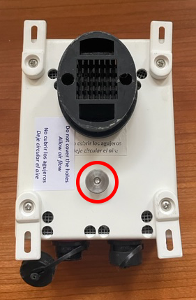
- Unfasten the case, using the thumb screw highlighted in the photo below. Note: it is not necessary to remove the four corner screws.
Step 2
- Carefully open the case to reveal the circuit board inside.
- Loosen the nine screws circled in yellow in the picture, which connect the lid to the circuit board.
Note: the four screws circled in red may be used to connect the optional Pressure and Relative Humidity Sensor. Owners of the Hydreon version will have more connections, but the same process applies. Be sure to note the order of the connections, preferably by taking a photo prior to disconnecting the wires.
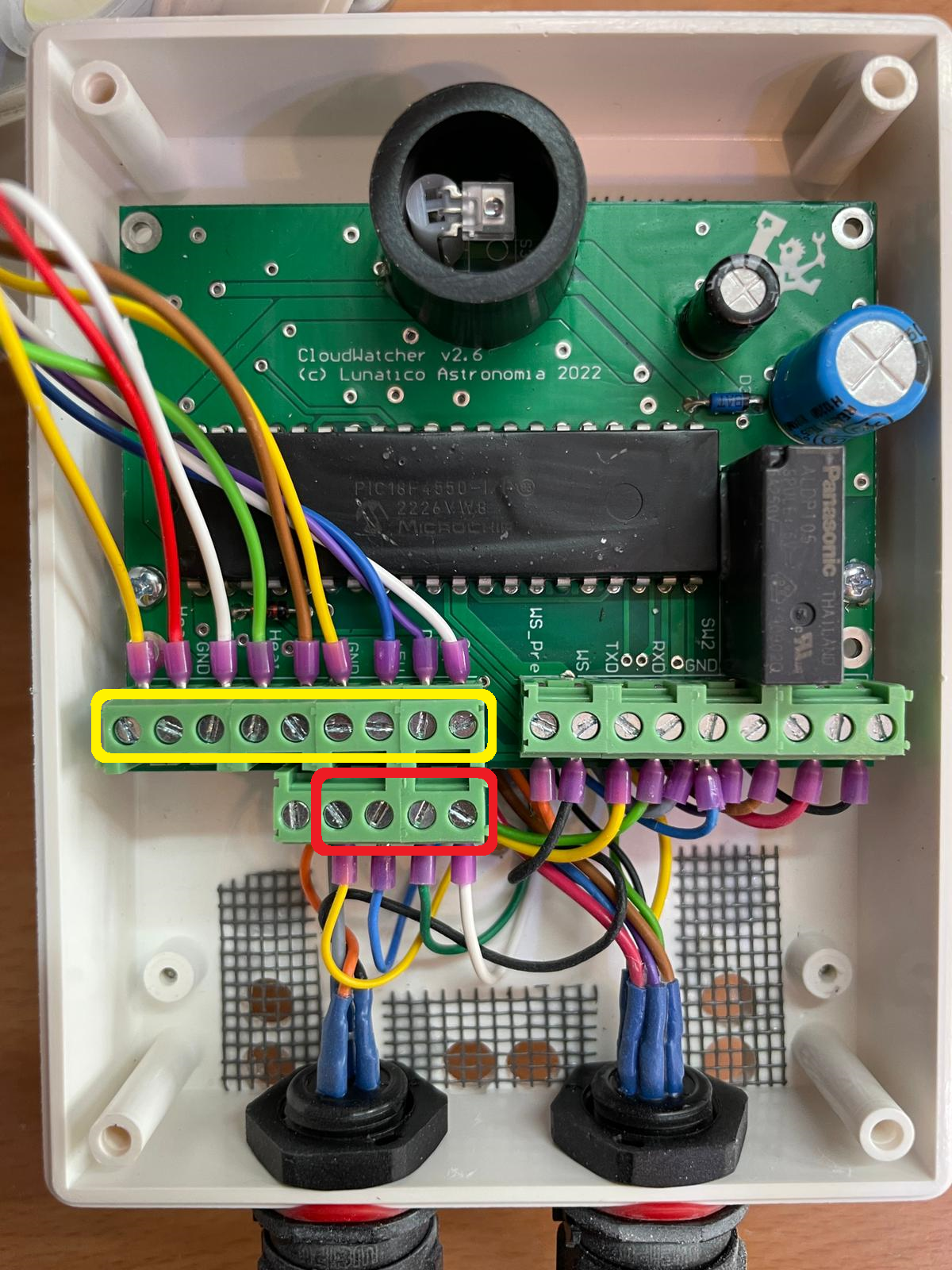
CloudWatcher with Atmospheric Pressure and Relative Humidity Sensor
- Remove the old lid.
Step 3
- Prepare the new lid for connection.
Critically important: connect the wires in the correct order. Please take the time to check that the wires are connected in the correct sequence—failure to do so may cause irreparable damage to your CloudWatcher. Be careful not to damage the coating of the rain sensor during installation.
- Use the picture from Step 2 to confirm that the lid has been correctly connected to the circuit board.
Step 4
- Carefully attach the lid to the case and secure it with the thumb screw.
- If possible, test the unit before redeploying it to your observatory.
Should you encounter any problems during or after this repair, please contact support@lunaticoastro.com.
Bonus: replacing the PCB
For detailed instructions see: Connecting the CW Board.
Replacing the CloudWatcher's PCB comes down to unscrewing the screws, removing the wires, and then connecting them to the new PCB in the same order—again, we recommend you take pictures of the original layout to ensure you get the order right.
The only thing worth noting is that some older versions of the CloudWatcher include wires which share one screw terminal, whereas recent PCBs have two different rows of terminals to make the connection easier. In the image below, each terminal marked in red has a matching terminal marked in yellow:
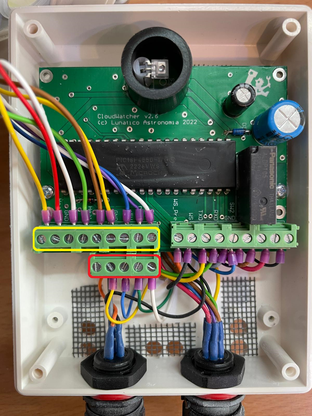
What you need to do if your CloudWatcher has two wires sharing one terminal is connect one to the appropriate yellow terminal and the other to the opposing red one—again, these two terminals are connected, so which goes where does not matter.