What do you need?
You'll just need a flat screwdriver.
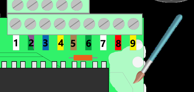
If you have access to PlastiDip Clear®, it will be a good idea to use it on top of the screws that go from the board into the box. As you can see below, we use it to cover the whole board. This will prevent humidity condensation from damaging the board.
Things to consider
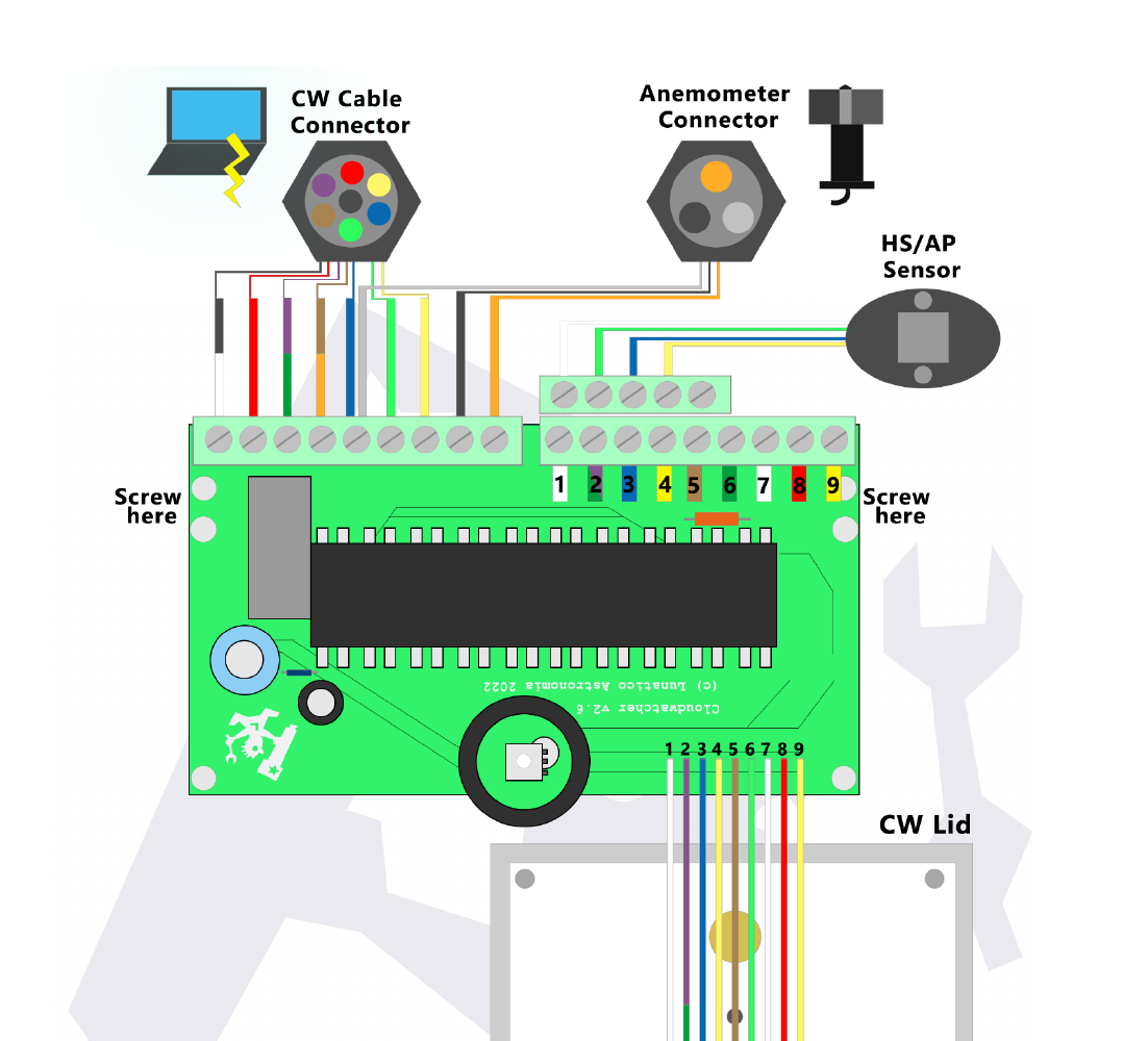
- Some cables vary in colour. As you will see in the diagram further down, green and purple cables are often interchanged in the CW cable connector, CW lid and RH/AP sensor. This is because our manufacturer does not always have access to the same cables. If a cable has a different colour than the ones appearing in the diagram, compare it to the rest of the cables to find out what pin it can be plugged into. If you have any doubts, please contact us.
- The board has two screw holes on each side of the top. This happens because there are several box and lid models out there. Compare the position of the board to the little window on the lid. The correct screw hole will be the one that places the light sensor in the middle of this window.
Note that this picture approximates the position of the sensor and cylinder—in reality it will never be completely centred.

- Cables must not be visible through the window. Sometimes when closing the CloudWatcher you might notice that the lid cables are covering the "view" of the light sensor. Make sure the cables get out of the way when closing the lid.

- Apply PlastiDip Clear® over the screws. It's a good idea to give this extra protection to the board after securing the PCB. Just apply one layer in the surroundings of the screws and wait for it to dry before closing the CloudWatcher. This is optional, but recommended.
- Make sure the box has its two risers. Your box should have one riser on each of the screw holes. If one or both are missing, use the ones included with the PCB. You can glue them with Loctite® or any other equivalent product.
- Installing the Relative Humidity/Atmospheric Pressure sensor. You might have to install this accessory too—see the lid replacement guide.
- If you have any further questions about installing the PCB and/or the lid, please contact us through support@lunaticoastro.com. You are responsible for the correct installation of the spare parts. Following the instructions will make it an easy and safe procedure, but if you encounter any difficulties, we are here to help.
The explanatory diagram